
Strength, Stiffness and Impact Resistance
What material datasheets tell us — and what they don’t.
1. Introduction
In this article, we will look at three mechanical properties that are particularly relevant to us:
Strength, stiffness and impact resistance.
We will see what they mean and how to understand the values found in material datasheets.
Comparing materials, however, is not always easy. Manufacturers may use different test methods or omit important information. This is particularly relevant for 3D-printed materials, where printing orientation and layer bonding can significantly affect the results.
2. Strength — How Much Stress Can It Withstand?
Strength tells us how much stress a material can withstand before it fails.
In a tensile test, we pull a specimen until it breaks.
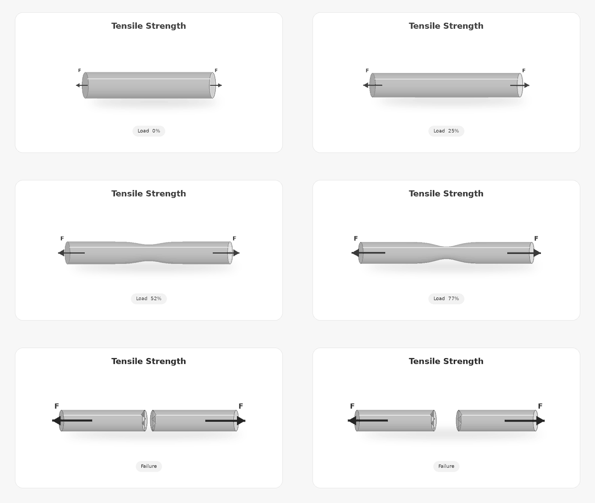
Because a thicker specimen can withstand more force simply because there is more material, we compare stress rather than force:
Stress = Force / Area
Stress is normally expressed in MPa, where:
1 MPa = 1 N/mm²
For example, if a 10 mm² specimen is subjected to 500 N:
500 N / 10 mm² = 50 MPa
The Tensile Strength is the maximum tensile stress reached during the test.
Higher Tensile Strength → more stress before failure.
3. Stiffness — How Much Does It Deform?
Stiffness tells us how much a material deforms when a load is applied.
Strength and stiffness are not the same. A material can be very stiff but break at a relatively low stress, while another can deform more before breaking.
During a tensile test, we can measure how much the specimen stretches:
Strain = Change in length / Original length
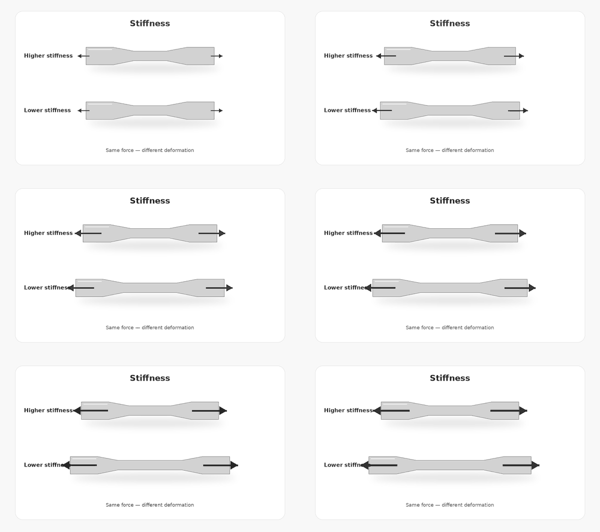
By comparing stress and strain in the elastic region, we obtain the Young’s Modulus, or Tensile Modulus.
Young’s Modulus = Stress / Strain
A higher modulus means less deformation under the same stress:
Higher Modulus → stiffer material.
Stiffness can also be measured in other ways, such as flexural, compressive or shear modulus, depending on how the load is applied.
The important distinction is:
Tensile Strength → How much stress can it withstand?
Tensile Modulus → How much will it deform?
4. Impact Resistance — What Happens Under a Sudden Load?
A material can perform well under a slowly applied load but behave very differently when it receives a sudden impact.
Impact resistance tells us how well a material can absorb an impact without breaking.
A common method is a pendulum impact test, such as Charpy or Izod.
A pendulum is released from a known height, strikes the specimen and continues with less energy:
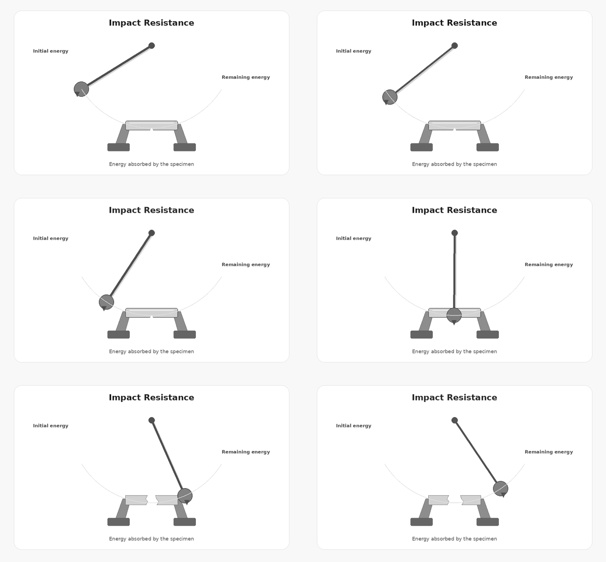
Initial Energy − Remaining Energy = Energy Absorbed by the Specimen
Impact results are commonly expressed in J or kJ/m².
An important detail is whether the specimen is notched or unnotched. A notch creates a controlled stress concentration and can significantly change the result.
5. Reading a Material Datasheet
Some common properties we can find are:
| Property | Unit | What Does It Tell Us? |
|---|---|---|
| Tensile Strength | MPa | How much tensile stress can it withstand? |
| Tensile Modulus | MPa / GPa | How stiff is it in tension? |
| Elongation at Break | % | How much can it stretch before breaking? |
| Impact Strength | kJ/m² | How well does it resist an impact? |
But there is an important problem:
The number alone is not enough.
6. Why Comparing Datasheets Can Be Difficult
Impact Resistance
Let’s compare some values reported for common PLA filaments:
| Material | Impact Resistance | Test |
|---|---|---|
| Bambu PLA Basic | 26.6 kJ/m² | Charpy, unnotched, XY |
| PolyMax PLA | 38.9 kJ/m² | Charpy, notched, XY |
| eSUN PLA+ | 5.5 kJ/m² | Izod, XY |
| SUNLU PLA+ | 10 kJ/m² | Izod, notched, XY |
The differences are huge, but we cannot simply say that 38.9 kJ/m² is better than 5.5 kJ/m².
Some manufacturers use Charpy, others Izod, and specimens may be notched or unnotched. These differences can significantly affect the result.
For 3D-printed materials, printing orientation is also very important. In the Z direction, the impact depends much more on the bond between layers.
For example, eSUN reports:
| Printing Orientation | Izod Impact Resistance |
|---|---|
| XY | 5.5 kJ/m² |
| Z | 2.51 kJ/m² |
Same material and same test, but the Z result is less than half the XY value.
When orientation is not specified, the reported value is likely to correspond to XY, as this generally gives better mechanical results. However, unless specified by the manufacturer, it should be treated as unknown.
So, to compare impact values properly, we need to know the test method, whether the specimen was notched, and its printing orientation.
Tensile Modulus
We find a similar problem when comparing stiffness:
| Material | Modulus | Type |
|---|---|---|
| Bambu PLA Basic | 2750 MPa | Bending Modulus, XY |
| PolyMax PLA | 2151 MPa | Young’s Modulus, XY |
| eSUN PLA+ | 2888 MPa | Flexural Modulus, XY |
| SUNLU PLA+ | 2750 MPa | Flexural Modulus, XY |
Although all these values describe stiffness, they do not come from the same test.
Young’s Modulus is obtained in tension, while Flexural or Bending Modulus is obtained by bending the specimen. They are related, but should not be treated as exactly the same property.
Orientation also affects stiffness. PolyMax, for example, reports:
| Printing Orientation | Young’s Modulus |
|---|---|
| XY | 2151 MPa |
| Z | 1984 MPa |
Interestingly, the difference is much smaller than we saw for impact resistance.
A Z-printed specimen can therefore have a similar initial stiffness to an XY specimen but still fail much earlier because of weaker layer bonding.
7. Testing Materials at RC Sailing Lab
This is why we are preparing our own material testing system at RC Sailing Lab.
Rather than simply repeating standardized datasheet tests, we want to compare materials under conditions closer to the way we actually build our boats.
For impact testing, we are developing a pendulum impact machine and a specimen designed to represent a typical section of a hull, reproducing characteristics such as wall thickness, printing direction and layer structure.
The principle is simple:
Different materials. Same geometry. Same impacts.
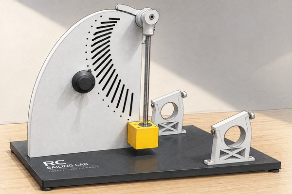
We will measure the energy to failure, but also observe how the specimen fails: whether the fracture follows the layers, whether the damage remains localized or produces a larger catastrophic failure, and whether repeated specimens behave consistently.
This can tell us not only about impact resistance, but also about layer bonding and printing consistency.
We are also preparing a tensile testing machine to measure Tensile Strength and Tensile Modulus under controlled conditions and in different printing orientations.
And the tests will not be limited to filaments. We also plan to test fiberglass laminates.
Our aim is to create comparable data for the materials we actually use, as well as new and emerging materials that show potential..
How stiff are they? How strong are they? How much impact can they absorb? How do they fail?
These tests will not replace standardized laboratory testing. They will give us comparative data under controlled conditions designed around the way we actually manufacture IOM boats.
Once the equipment and testing procedure are ready, we will start sharing the results.